
Bonded anchor mortar cartridge W-VD
Compound anchor, mortar cartridge, W-VD
ANC-(W-VD)-M10
Art.-no. 5915010080
EAN 4058794712421


Register now and access more than 125,000 products
- Individual fastening of non-cracked concrete:
- W-VD-A anchor rod (with approval) or W-VD-IG female thread anchor (with approval)
- Compound anchor, cartridge system (pre-mixed mortar quantities in a glass cartridge)
- Anchor rod is placed while rotating and pushing (rotational movement mixes the two mortar components)
- The hardened composite mortar seals the drill hole as far as possible
- Attachment with low expansion pressure allows small axial and edge clearances
- Anchoring occurs due to combination of mortar, anchor rods and anchoring base. Galvanised steel anchor rod in sizes M8, M10, M12, M16, M20 and M24
- European Technical Approval ETA-06/0074: Individual fixing point + uncracked concrete (anchor rod W-VD-A)
- Zinc-plated steel: European Technical Approval ETA-06/0074
- Fire resistance: F30, F60, F90, F120: Exposure to fire on one side according to DIN EN 1363-1:1999-10
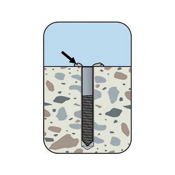
Clean the drill hole: 1x blow out, 1x brush out, 1x blow out, 1x brush out
Insert anchor rod using hammer drill or impact drill in rotation + impact mode.
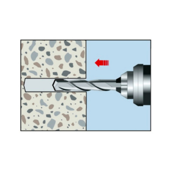
Drill the hole
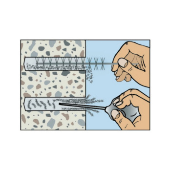
1x blow-out
1 pc.
1x blow-out
1 pc.
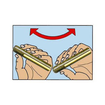
Resin must flow like honey when cartridge is warm to the touch
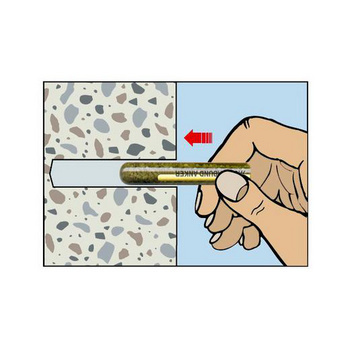
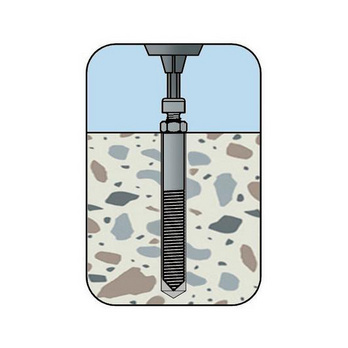
Push in cartridge
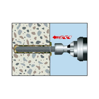
Set threaded rod rotating/impacting
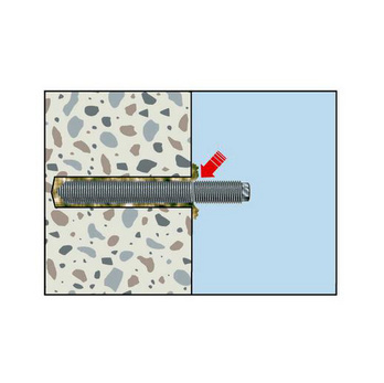
Visual check of mortar filling quantity
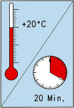
Observe the hardening time
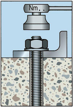
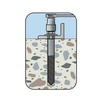
Mount component, apply torque
Drill the hole
1x blow-out
1 pc.
1x blow-out
1 pc.
Resin must flow like honey when cartridge is warm to the touch
Push in cartridge
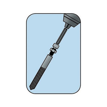
Mount setting tool
Set threaded rod rotating/impacting
Visual check of mortar filling quantity
Observe the hardening time
Mount component, apply torque
- European Technical Approval ETA-06/0074: Individual fixing point + uncracked concrete (anchor rod W-VD-A)
- Zinc-plated steel: European Technical Approval ETA-06/0074
- Fire resistance: F30, F60, F90, F120: Exposure to fire on one side according to DIN EN 1363-1:1999-10
Datasheets(X)
CAD data (available after login)

- Anchorage with European Technical Approval in uncracked concrete (compression zone)
- The anchor may be used for anchorages with predominantly static loads (e.g. own weight, fittings, stored materials) or quasi-static loads
- Installation in dry or wet concrete (normal weight concrete with a concrete compressive strength of min. C20/25 and max. C50/60)
- The temperature in the area surrounding the mortar must not exceed +50°C and, in the short-term, +80°C
- For use in concrete < C20/25 and pressure-resistant natural stone (without approval)
- Suitable for fastening metal structures, metal profiles, brackets, base plates, supports, wooden structures, beams etc.
Type description | W-VD M10 |
Effective anchoring depth (h ef) | 90 mm |
Suitable for anchor rod | M10 |
Nominal drill-bit diameter (d 0) | 12 mm |
Drill hole depth (h 0) | 90 mm |
Suitable cleaning-brush diameter | 13 mm |
Approval | ETA-06/0074 |
Min./max. processing temperature | -5 to 35 °C |
Torque during anchoring (T inst) | 20 Nm |
Shelf life from production/conditions | 18 Month / cool and dry storage area, 5°C to 25°C |
Minimum component thickness (h min) | 120 mm |
Min. centre-to-centre distance (s min) | 45 mm |
Centre-to-centre distance (s cr, N) | 180 mm |
Min. edge clearance (c min) | 45 mm |
Edge clearance (c cr, N) | 90 mm |
| Performance data for bonded anchor capsule system W-VD/S | ||||||||
| Anchor diameter | M8 | M10 | M12 | M16 | M20 | M24 | ||
| Admissible centric tension load1) on an individual anchor without the influence of the edge distance | Compressive zone (uncracked concrete C20/25 M8: s ≥ 3 hef, c ≥ 1.5 hef M10-M24: s ≥ 2 hef, c ≥ 1 hef) | Nadm [kN] = C20/25 50°C2)/80°C3) | 7,9 | 11,9 | 15,9 | 19,8 | 29,8 | 35,7 |
| Admissible shear load1) on an individual anchor without the influence of the edge distance | Compressive zone (uncracked concrete C20/25, c ≥ 10 hef) | Vadm [kN] = C20/25 | 5,1 | 8,0 | 12,0 | 22,3 | 34,9 | 50,3 |
| Admissible bending moment | Madm [Nm] | 10,9 | 21,1 | 37,1 | 94,9 | 185,7 | 320,6 | |
| Fire resistance rating | F30 [kN] | 2,3 | 3,64 | 5,26 | 9,79 | 15,28 | 22,01 | |
| F60 [kN] | 1,29 | 2,04 | 3,07 | 5,72 | 8,93 | 12,86 | ||
| F90 [kN] | 0,79 | 1,3 | 2,0 | 3,68 | 5,75 | 8,28 | ||
| F120 [kN] | 0,53 | 1,0 | 1,5 | 2,67 | 4,16 | 6,0 | ||
| Characteristic values | ||||||||
| Minimum spacing | smin [mm] | 40 | 45 | 55 | 65 | 85 | 105 | |
| Spacing | scr,N [mm] | 240 | 180 | 220 | 250 | 340 | 420 | |
| Minimum edge distance | cmin [mm] | 40 | 45 | 55 | 65 | 85 | 105 | |
| Edge distance | ccr,N [mm] | 120 | 90 | 110 | 125 | 170 | 210 | |
| Minimum member thickness | hmin [mm] | 110 | 120 | 140 | 160 | 220 | 260 | |
| Effective anchorage depth | hef [mm] | 80 | 90 | 110 | 125 | 170 | 210 | |
| Nominal drill diameter | d0 [mm] | 10 | 12 | 14 | 18 | 25 | 28 | |
| Diameter of cutting edges | dcut ≤ [mm] | 10,5 | 12,5 | 14,5 | 18,5 | 25,5 | 28,5 | |
| Drill hole depth | h0 ≥ [mm] | 80 | 90 | 110 | 125 | 170 | 210 | |
| Through hole in the component being connected | df ≤ [mm] | 9 | 12 | 14 | 18 | 22 | 26 | |
| Torque while installing anchor | Tinst = [Nm] | 10 | 20 | 40 | 80 | 120 | 180 | |
| Cleaning brush diameter | D [mm] | 10,8 | 13 | 15 | 19 | 27 | 29 | |
| 1) The partial safety factors of the resistances regulated in the approval and a partial safety factor of the actions of γF = 1.4 have been taken into account. For information on combining tensile and shear loads, influence of the edge distance and anchor groups, please refer to the European Technical Approval Guidelines (ETAG), Annex C 2) Maximum long-term temperature 3) Maximum short-term temperature | ||||||||
| Performance data for bonded anchor internal thread capsule system W-VD-IG/S, W-VD-IG/A4
| |||||
| Internal thread | M8 | M10 | M12 | M16 | |
| Recommended tensile load Compressive zone (uncracked concrete C20/25) | Nrec [kN] = C20/25 | 7,0 | 11,1 | 16,1 | 25,0 |
| Recommended shear load Compressive zone (uncracked concrete C20/25) | Vrec [kN] = C20/25 | 8,0 | 8,3 | 9,7 | 19,5 |
| Recommended bending moment | Mrec. [Nm] | 10,7 | 21,4 | 37,4 | 94,9 |
| Characteristic values | |||||
| Minimum spacing | smin [mm] | 45 | 45 | 50 | 75 |
| Spacing | scr,N [mm] | 225 | 225 | 250 | 300 |
| Minimum edge distance | cmin [mm] | 45 | 45 | 50 | 75 |
| Edge distance | ccr,N [mm] | 115 | 115 | 125 | 150 |
| Minimum member thickness | hmin [mm] | 140 | 140 | 150 | 170 |
| Effective anchorage depth | hef [mm] | 90 | 90 | 100 | 120 |
| Nominal drill diameter | d0 [mm] | 14 | 16 | 18 | 25 |
| Drill hole depth | h1 ≥ [mm] | 90 | 90 | 100 | 120 |
| Through hole in the component being connected | df ≤ [mm] | 9 | 12 | 14 | 18 |
| Torque while installing anchor | Tinst = [Nm] | 10 | 20 | 40 | 80 |
| Performance data for bonded anchor capsule system W-VD/A4, W-VD/HCR | ||||||||
| Anchor diameter | M8 | M10 | M12 | M16 | M20 | M24 | ||
| Admissible centric tension load1) on an individual anchor without the influence of the edge distance | Compressive zone (uncracked concrete C20/25 M8: s ≥ 3 hef, c ≥ 1.5 hef M10-M24: s ≥ 2 hef, c ≥ 1 hef) | Nadm [kN] = C20/25 50°C2)/80°C3) | 7,9 | 11,9 | 15,9 | 19,8 | 29,8 | 35,7 |
| Admissible shear load1) on an individual anchor without the influence of the edge distance | Compressive zone (uncracked concrete C20/25, c ≥ 10 hef) | Vadm [kN] = C20/25 | 6,0 | 9,2 | 13,3 | 25,2 | 39,4 | 56,8 |
| Admissible bending moment | Madm [Nm] | 11,9 | 23,8 | 42,1 | 106,7 | 207,9 | 359,4 | |
| Fire resistance rating | F30 [kN] | 2,3 | 3,64 | 5,26 | 9,79 | 15,28 | 22,01 | |
| F60 [kN] | 1,29 | 2,04 | 3,07 | 5,72 | 8,93 | 12,86 | ||
| F90 [kN] | 0,79 | 1,3 | 2,0 | 3,68 | 5,75 | 8,28 | ||
| F120 [kN] | 0,53 | 1,0 | 1,5 | 2,67 | 4,16 | 6,0 | ||
| Characteristic values | ||||||||
| Minimum spacing | smin [mm] | 40 | 45 | 55 | 65 | 85 | 105 | |
| Spacing | scr,N [mm] | 240 | 180 | 220 | 250 | 340 | 420 | |
| Minimum edge distance | cmin [mm] | 40 | 45 | 55 | 65 | 85 | 105 | |
| Edge distance | ccr,N [mm] | 120 | 90 | 110 | 125 | 170 | 210 | |
| Minimum member thickness | hmin [mm] | 110 | 120 | 140 | 160 | 220 | 260 | |
| Effective anchorage depth | hef [mm] | 80 | 90 | 110 | 125 | 170 | 210 | |
| Nominal drill diameter | d0 [mm] | 10 | 12 | 14 | 18 | 25 | 28 | |
| Diameter of cutting edges | dcut ≤ [mm] | 10,5 | 12,5 | 14,5 | 18,5 | 25,5 | 28,5 | |
| Drill hole depth | h0 ≥ [mm] | 80 | 90 | 110 | 125 | 170 | 210 | |
| Through hole in the component being connected | df ≤ [mm] | 9 | 12 | 14 | 18 | 22 | 26 | |
| Torque while installing anchor | Tinst = [Nm] | 10 | 20 | 40 | 80 | 120 | 180 | |
| Cleaning brush diameter | D [mm] | 11 | 13 | 16 | 20 | 27 | 30 | |
| 1) The partial safety factors of the resistances regulated in the approval and a partial safety factor of the actions of γF = 1.4 have been taken into account. For information on combining tensile and shear loads, influence of the edge distance and anchor groups, please refer to the European Technical Approval Guidelines (ETAG), Annex C 2) Maximum long-term temperature 3) Maximum short-term temperature | ||||||||
Last viewed

Time-Sert® drill bit

Multiclean cleaning liquid

Washer with large outside diameter DIN 9021 (with large outside diameter), A2 stainless steel, plain

Drop-in anchor W-ED/S

Zinc clip-on wheel weight For car steel rims

WÜPOFAST® A2 PZ Particle board screw

Specially fused alumina sanding tip, pink

3/8 inch socket wrench insert metric, hexagon, short

Mechanic's glove

Hex. standard mount, size 11 for drills