


ASSY® 4 A2 CSMP timber screw A2 stainless steel plain partial thread countersunk milling pocket head
ASSY 4 A2 CSMP sst A2 PT cs mill. pckt RW
SCR-CS-CTRHD-WO-A2-RW40-8X100/60
Art.-no. 0187480100
EAN 4061975615473


Register now and access more than 125,000 products
Ideal power transmission thanks to RW drive
- More power due to larger contact area at the bit
- More stability, one-handed working, precise positioning due to the tight-fit recess and perfect fit of the bit
- Fewer bit changes, one bit for many screw diameters
- Compatibility with previous AW drive
Higher breaking torque
- Higher power transmission in hardwoods due to reinforced, asymmetrical thread flank geometry of the single thread
- Better anchoring thanks to higher thread flanks
Smooth thread start ensures optimised recessing and biting of the screw
- Reduced splitting effect due to displacement effect of the dome-shaped milling elements in the tip
- Friction-reduced thread rotation allows reduction of the screw-in force to be applied
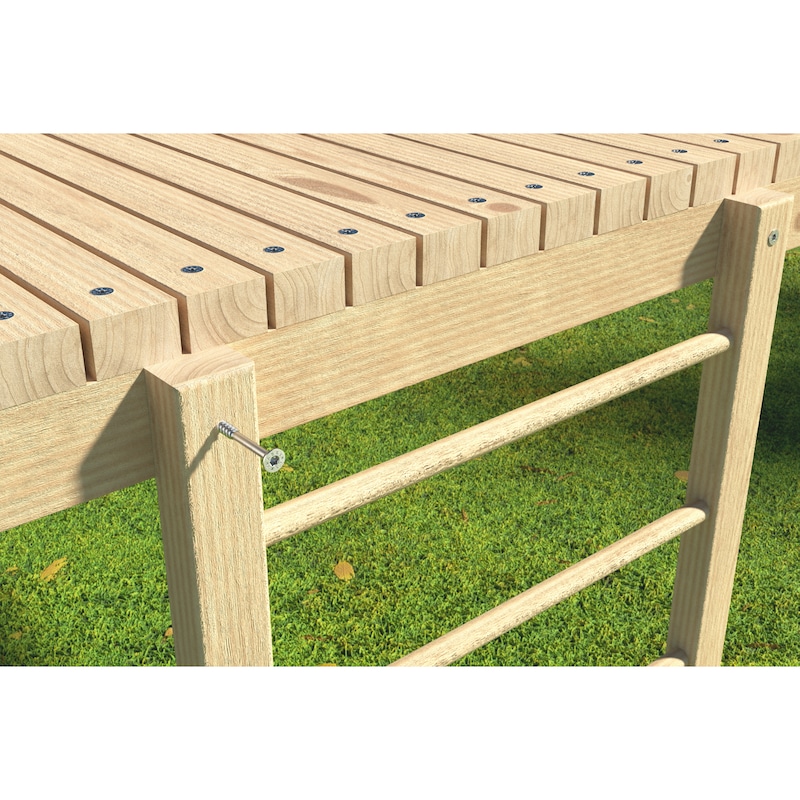
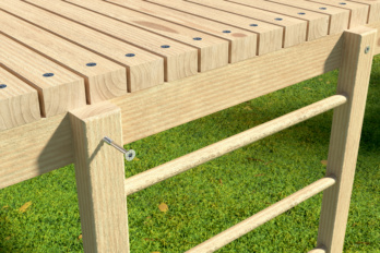
Stainless mounting for accessible wood connections in outdoor areas exposed to weathering
- Made of austenitic, non-magnetic and non-rusting A2 stainless steel
- Can be used in rural or urban environments or industrial atmospheres without significant exposure to chlorides or SO2
- With friction-reducing slide coating for easy fastening
ETA-11/0190 approved
- Austenitic stainless steel is characterised by a high degree of corrosion resistance against aggressive industrial air, sea air, tap water, river water, mine water and salt water, as well as woods containing tannic acid. It is resistant to acid to a certain extent and not suitable for atmospheres containing chlorine gas
- We recommend using the Würth software or the corresponding design aids for planning and dimensioning your assembly. Use the Würth timber construction software for dimensioning of ASSY screws from a diameter of 5 mm
- ASSY 4, ASSYplus 4 and ASSYplus 4 FT chipboard screws are optimised for use in wood and wood materials. For applications in plastic anchors where load capacity can also be reduced, use only screws without an optimised thread tip (tip with milling ribs, drill tip, self-clearing groove etc.), such as the ASSY D screws with countersunk head or pan head
ETA-11/0190 approved
The requirements of the European Technical Approval (ETA) must be observed
Datasheets(X)

For wood-wood connections designed to pull together
The partial thread starting immediately below the shank allows for wood-wood connections designed to pull together. The screw thread is positioned entirely in the lower component once screwed in.
Can be used for outdoor applications and utilisation class 3
- ASSY screws are approved for quasi-static loads
- For optimum use of the screw, the right-size RW bit must be used
- Partial-thread screws are ideal for connecting wooden components. To achieve optimum assembly of the components, the components to be fixed must not be thicker than the length of the shank
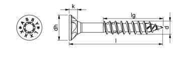 | |
Nominal diameter (d) | 8 mm |
Length (l) | 100 mm |
Thread length (lg) | 60 mm |
Head type | Countersunk milling pocket head |
Head details | Milling pockets |
Head diameter (dh) | 15 mm |
Head height (k) | 4.9 mm |
Internal drive | RW40 |
Thread type | Wood screw thread |
Thread design | Partial thread |
Thread form | Single start thread |
Core diameter | 5.1 mm |
Shape of tip | Tip with hilltop milling cutter |
Angle of the tip | 34 Degree |
Material | Stainless steel A2 |
Surface | Plain |
Min./max. screw-in angle | 0-90 Degree |
Suitable for use in the following materials | Wood, Derived timber product, Softwood, Board ply wood (BSP), Hardwood, LVL |
Area of application | Façades, Terrace, Fence, Structural woodwork, Element construction, Timber panel construction, Timber construction, Wet areas, Play equipment, Outdoors |
Suitable machines | Würth BS 18-A Power |
Screw requiring approval | Yes |
Approval | ETA-11/0190 |
RoHS-compliant | Yes |
| Remarks: | |
| • | The values apply to a minimum thickness of the component of 10 x d |
| • | The minimum insertion depth of the screws in the front surface of the cross laminated timber is 10 x d |
| • | The requirements of the respective manufacturers of cross laminated timber components must be observed in the same way |
| Minimum clearances in mm for screws in cross laminated timber | |||||||||||||
| Side surfaces | Front surfaces | ||||||||||||
| d in mm | a1 | a2 | a3,t | a3,c | a4,t | a4,c | d in mm | a1 | a2 | a3,t | a3,c | a4,t | a4,c |
| 4 x d | 2.5 x d | 6 x d | 6 x d | 6 x d | 2.5 x d | 10 x d | 4 x d | 12 x d | 7 x d | 6 x d | 3 x d | ||
| 8 | 32 | 20 | 48 | 48 | 48 | 20 | 8 | 80 | 32 | 96 | 56 | 48 | 24 |
| Edge distances in cross laminated timber under shear load | |||
| Remarks: | |
| • | If the spacing between the screws in the direction of the grain and from the end of the end of the grain is at least 25 x d, the spacing to the unstressed edge may be reduced to 3 x d, even with component thicknesses t < 5 x d |
| • | The minimum thicknesses of the components to be connected must be observed in accordance with ETA-11/0190 (A.2.4.2) |
| • | When using woods at risk of splitting, the screws should always be pre-drilled and the |
| • | For steel-wood connections, the minimum distances (a1, a2) can be multiplied by a coefficient of 0.7 |
| • | For wooden plate connections, the minimum distances (a1, a2) can be multiplied by a coefficient of 0.85 |
| • | For Douglas fir wooden components, the minimum clearances in the direction of the grain must be increased by 50% |
| Edge distances in wood under shear load | |||||
| Bracket between force and grain direction α = 0° | Bracket between force and grain direction α = 90° | ||||
| Stressed end of the end grain -90° < < α 90° | Unstressed end of the end grain 90° < α < 270° | Stressed edge 0° < α < 180° | Unstressed edge 180° < α < 360° | ||
| Remarks: | |
| • | The minimum distances are defined in accordance with EN 1995-1-1 tab. 8.6, where d is the male thread diameter |
| • | The minimum thicknesses of the components to be connected must be observed in accordance with ETA-11/0190 (A.2.4.3) |
| • | For combined shear and axial tensile loads, the minimum clearances for screws and shear stress must be used |
| Minimum clearances in mm for screws in wooden components | ||||
| DIN EN 1995-1-1 | a1 | a2 | a1,CG | a2,CG |
| ETA-11/0190 | a1 | a2 | a1,c | a2,c |
| d in mm | 7 x d | 5 x d | 10 x d | 4 x d |
| 8 | 56 | 40 | 80 | 32 |
| Edge distances in wood with an axial load | |||
| Pre-drilling diameter according to ETA-11/0190 in mm | |
| d in mm | 8 |
| Softwood | 5,0 |
| Hardwood | 6,0 |
| BauBuche1) | 6,5 |
| 1) According to 1459 expert report SWG ASSY BauBuche | |
| Minimum distances in mm for pre-drilled screws in softwood, hardwood, BauBuche | |||||||||||||
| Bracket between force and grain direction α = 0° | Bracket between force and grain direction α = 90° | ||||||||||||
| d in mm | a1 | a2 | a3,t | a3,c | a4,t | a4,c | d in mm | a1 | a2 | a3,t | a3,c | a4,t | a4,c |
| 5 x d | 3 x d | 12 x d | 7 x d | 3 x d | 3 x d | 4 x d | 4 x d | 7 x d | 7 x d | 7 x d | 3 x d | ||
| 8 | 40 | 24 | 96 | 56 | 24 | 24 | 8 | 32 | 32 | 56 | 56 | 56 | 24 |
| 1) The minimum clearances are specified in accordance with DIN EN 1995-1-1 tab. 8.2 for pre-drilled nail holes, where d is the male thread diameter 2) The minimum distances between 0° < α < 90° force to the direction of the grain can be determined more precisely in accordance with EN 1995-1-1 tab. 8.2 | |||||||||||||
| Minimum distances in mm for non-pre-drilled screws in wooden components 420 kg/m3 ≤ ρk ≤ 500 kg/m3 | |||||||||||||
| Bracket between force and grain direction α = 0° | Bracket between force and grain direction α = 90° | ||||||||||||
| d in mm | a1 | a2 | a3,t | a3,c | a4,t | a4,c | d in mm | a1 | a2 | a3,t | a3,c | a4,t | a4,c |
| 15 x d | 7 x d | 20 x d | 15 x d | 7 x d | 7 x d | 7 x d | 7 x d | 15 x d | 15 x d | 12 x d | 7 x d | ||
| 8 | 120 | 56 | 160 | 120 | 56 | 56 | 8 | 56 | 56 | 120 | 120 | 96 | 56 |
| 1) The minimum clearances are specified in accordance with DIN EN 1995-1-1 tab. 8.2 for non-pre-drilled nail holes, where d is the male thread diameter 2) The minimum distances also apply to screw diameter ≥ 5 mm in components made of BauBuche (ETA-14/0354) for component thicknesses of t ≥ 7 x d 3) The minimum clearances between 0° < α < 90° force to the direction of the grain can be fixed more precisely in accordance with EN 1995-1-1 tab. 8.2 4) Wooden components with ρk > 500 kg/m3 must always be pre-drilled | |||||||||||||
| Minimum distances in mm for non-pre-drilled screws in wooden components ρk ≤ 420 kg/m3 | |||||||||||||
| Bracket between force and grain direction α = 0° | Bracket between force and grain direction α = 90° | ||||||||||||
| d in mm | a1 | a2 | a3,t | a3,c | a4,t | a4,c | d in mm | a1 | a2 | a3,t | a3,c | a4,t | a4,c |
| 12 x d | 5 x d | 15 x d | 10 x d | 5 x d | 5 x d | 5 x d | 5 x d | 10 x d | 10 x d | 10 x d | 5 x d | ||
| 8 | 96 | 40 | 120 | 80 | 40 | 40 | 8 | 40 | 40 | 80 | 80 | 80 | 40 |
| 1) The minimum clearances are specified in accordance with DIN EN 1995-1-1 tab. 8.2 for non-pre-drilled nail holes, where d is the male thread diameter 2) The minimum distances between 0° < α < 90° force to the direction of the grain can be determined in accordance with DIN EN 1995-1-1 tab. 8.2 | |||||||||||||
Last viewed

HSS annular cutter

Plastic blind rivet with rounded mandrel

PE backfill sealant

1/2 inch socket wrench insert metric, hexagon, short

Mask Plus paintwork protection film

1-inch impact socket wrench insert hexagon, metric, short

Acrylic sealant interior S-Line

Welding cap WSC 9-12

Sealant smoothing agent

Electric planer EH 4